Smart RTU Solution
A remote terminal unit (RTU) is a microprocessor-controlled electronic device that interfaces objects in the physical world to a distributed control system or SCADA (supervisory control and data acquisition system) by transmitting telemetry data to the system and employing messages to control the connected objects from the supervisory system.
Automation technology is rapidly advancing, while the growing demands of utility owners for more cost-effective control systems must be met. New communication techniques, devices, and standard protocol interfaces, combined with the immense computing power of today’s hardware components, open the way to new concepts in the automation industry. Enilit RTU was built to meet the requirements of modern-day automation systems.
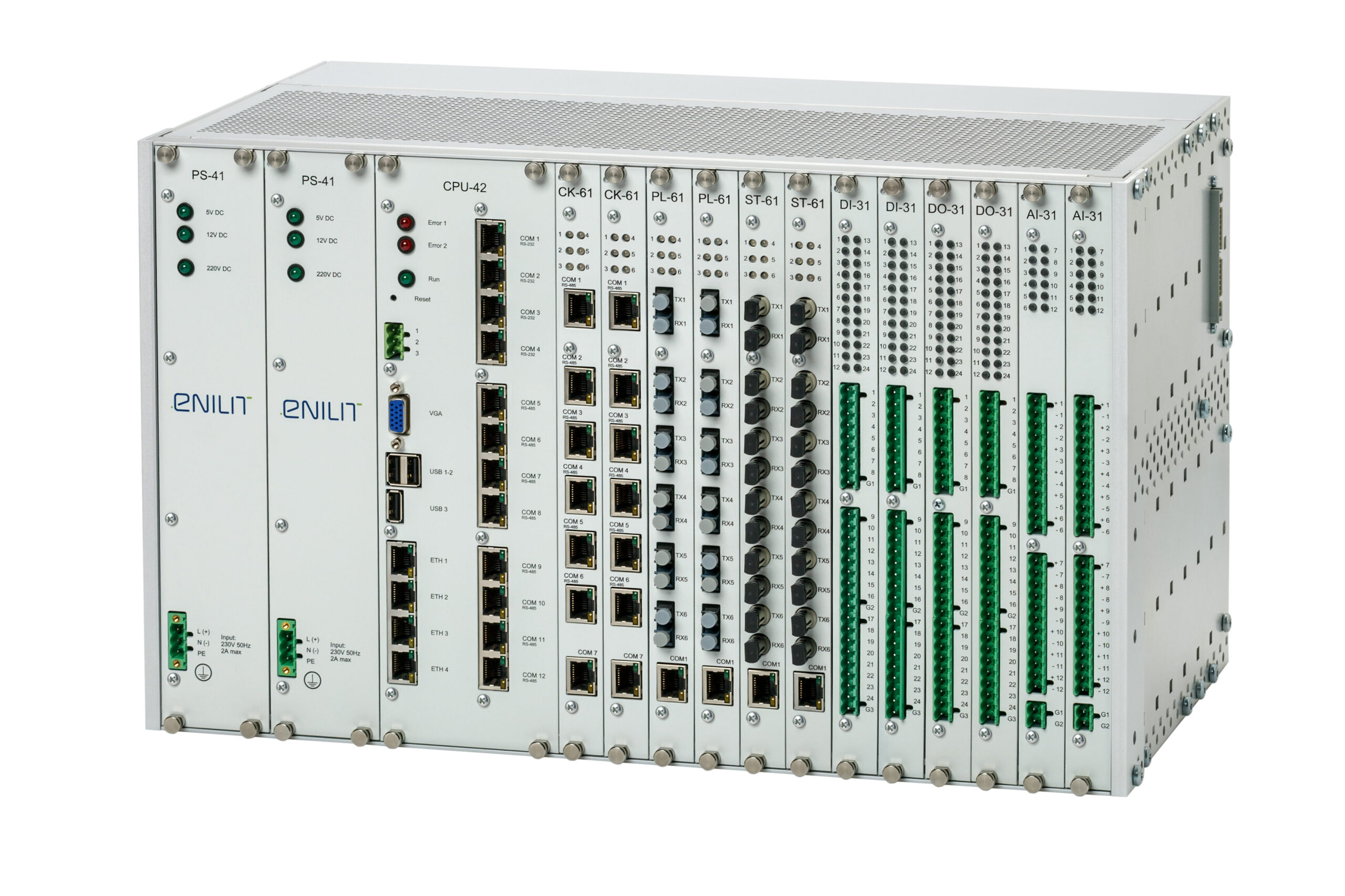
Free demo units available (subject to deposit payment).
Widely Applicable Enilit RTU System
Modular and Open Structure – Enilit RTU Is Our Solution for Automation

Electric power generation plants

Monitoring and control of chemical and petrochemical plants and pipelines

Traffic control systems (railways, metro, tramways, etc.)

Data acquisition and control in building engineering systems (escalators, lighting, air conditioning, etc.)

Electricity transmission and distribution networks

Environmental technology with measured data acquisition and remote evaluation

Supply networks of municipal and regional public utilities (gas, electricity, water, sewage, district heating, etc.)
Main RTU Advantages
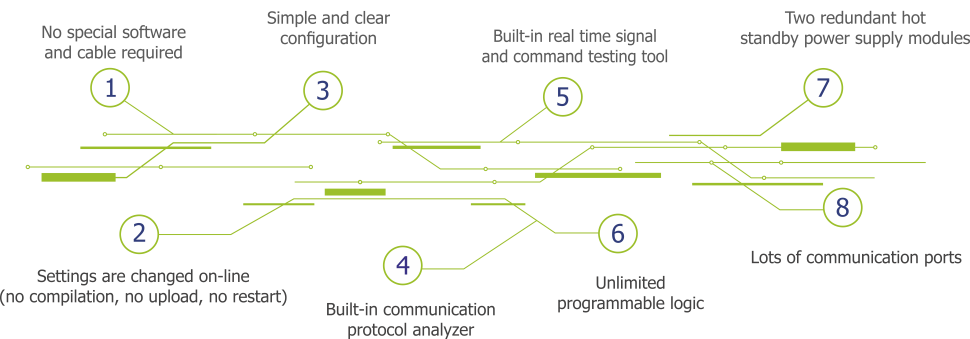
Enilit RTU – Flexible and Compatible Solution
RTU Connectivity and Comunication
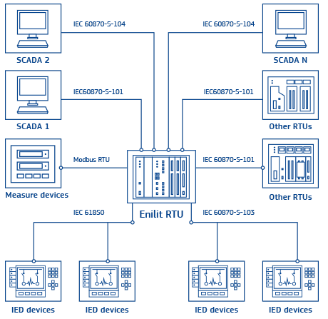
Enilit RTU offers a cost-effective solution for classic RTU functions. Gathering of direct-wired process information and transferring it to a higher-level control system is one of the primary tasks of the remote terminal unit Enilit RTU. Also, there are a lot of protection terminals, control, metering, and other automation devices that need to be connected in one system. Enilit RTU can communicate with various sub RTUs, IEDs, and upper RTUs, SCADA control centers using all supported protocols at the same time. Each communication port can be configured for different protocols independently.
RTU Configuration
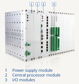
Enilit RTUs come in industry-standard 19-inch, 6U, frames that are made from high-quality aluminum. RTUs are configured by installing the required number of selected modules. If the standard frame can not house all the required modules, the second frame can be connected as an extension. The maximum connection distance between two frames – 15 m. RTU modules (i.e. Dl, DO, Al, AO, or communication modules) can be installed in any order according to the customer’s requirements. Any type of module can be installed in any free slot.
RTU standard supports:
- up to 2 PS modules;
- 1 CPU module;
- has 12 slots for I / O and communication modules.
RTU extended (each extension frame) supports:
- up to 2 PS modules;
- has 16 slots for I / O and communication modules.
RTU mini supports:
- up to 2 PS modules;
- 1 CPU module;
- has 1 slot for I / O or communication module.
RTU Modules
Power Supply (PS) Modules

Two redundant power supply modules can be installed;
The second module works as a redundant hot standby power supply, switching reaction time is immediate;
Input range:
- PS 21 : 230V AC / DC;
- PS 31 : 110V DC;
- PS 51 : 48V DC (16.5-75V DC).
Central Processing Unit (CPU) Modules

64-bit Intel Atom microprocessor of 1.6 Ghz, 2 GB Dynamic memory DRAM;
32GB SSD disk (for software, databases, events, waveforms, parameters);
4 pcs. Ethernet-based 10/100 BaseTx ports (not switched – all 4 ports are able to work with different information network gateway and have unique MAC)
12 pcs. of RS232/RS485 COM ports (RJ45 interface):
- CPU 41 has 12 x RS485 ports;
- CPU 42 has 4 x RS232 + 8 x RS485 ports;
- CPU 43 has 8 x RS232 + 4 x R5485 ports;
- CPU 44 has 12 x RS232 ports.
Digital Input (DI) Modules

24 pcs. optically isolated Dl with one common minus for each 8 inputs;
Input types: digital input, BCD code, pulse counter;
Each digital input can be configured as a single or double signal on the same Dl module;
LED indication for each digital input status;
Input range:
- Dl 11 : 24 Vdc (16 … 30V);
- Dl 21 : 48 Vdc (34 … 72V);
- Dl 31 : 110 Vdc (80 … 150V);
- Dl 41 : 220 Vdc (150 … 264V).
Digital Output (DO) Modules

24 pcs. single pole relays with one normally open (NO) contact;
Each digital output channel can be configured as Latch Type Short or Long Pulse Type and can be executed in either Direct Execute or Select Before Operate Execute manner;
Each digital output can be configured in a single or
double remote control or a set point output on the same module;
LED indication for each digital output status;
Contact ratings according to EN60947-5-1:
- AC15, 250 VAC, 3A;
- DC13, 24 VDC, 2A;
- DC13, 250 VDC, 0.2A.
Analog Input (AI) Modules AI-31

12 pcs. of independent optically isolated analog inputs;
Input range (current or voltage are selectable for each input by the internal jumper position):
- Al 31 current: -20mA to +20mA;
- Al 31 voltage: -10V to 10V;
Lower and upper range limits for each analogue input can be defined separately;
LED indication for each analog input status;
20 ms time tagging;
16 bits ADC.
Analog Output (AO) Modules AO-31

8 pcs. of independent optically isolated analog outputs;
- AO 31 current: -24mA to +24mA;
- AO 31 voltage: -12V to 12V;
Lower and upper range limits for each analog input can be defined separately;
LED indication for each analog output status;
20 ms time tagging;
Resolution in all ranges: 16 bit.
Communication Modules PL-61

Connector type: plastic optic;
Six communication channels can be used for RS serial type protocols as IEC 60870-5-101, IEC 60870-5-103, DNP 3.0 serial, Modbus serial and other;
Status LED indication for every channel;
1 pcs. of RS-485 port to connect to the CPU COM port via external cable.
Communication Modules CK-61

Connector type: RJ-45;
Six communication channels can be used for RS serial type protocols as IEC 60870-5-101, IEC 60870-5-103, DNP 3.0 serial, Modbus serial and other;
Status LED indication for every channel;
1 pcs. of RS-485 port to connect to the CPU COM port via external cable.
Communication Modules ST-61

Connector type – ST glass fiber optic;
Six communication channels can be used for RS serial type protocols as IEC 60870-5-101, IEC 60870-5-103, DNP 3.0 serial, Modbus serial and other;
Status LED indication for every channel;
1 pcs. of RS-485 port to connect to the CPU COM port via external cable.
Enilit CMS – Unique and User-Friendly Software
Enilit configuration and management software (CMS) was designed for easy and intuitive configuration of Enilit RTU.
Windows-based Enilit CMS tool enables users to configure I/O features, Master and Slave protocols, PLCs, Tag connections. Also, Enilit CMS performs live diagnostics at local stations and remote stations over TCP/IP.
Enilit CMS makes Enilit RTU a cost-efficient solution as it simplifies the installation and configuration process of Enilit RTU system:
- The configuration of Enilit RTU is carried out on-line on the device (no compilation, no upload, no restart), and no other software or cable is needed, which saves a lot of time during the commissioning or service;
- The built-in communication protocol analyzer, real-time signal and command testing tool allow users to see on-line the data received and sent through Enilit RTU, and to simulate each signal, command, or measurement from Enilit RTU through each of protocols.

Expanded Enilit RTU Functionality
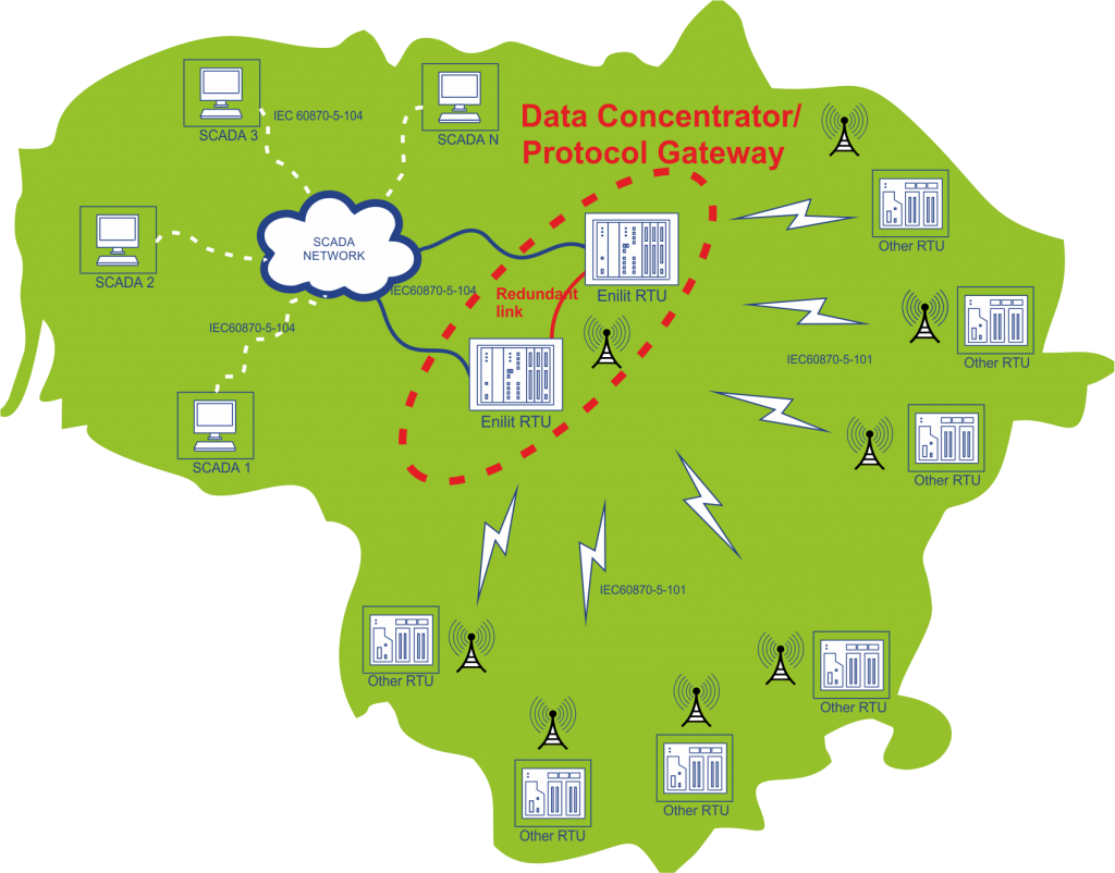
Data Concentrator / Protocol Gateway
A wide range of supported protocols and hardware ports makes Enilit RTU useful in any situation where a data concentrator or protocol gateway is needed. Protocol gateway monitors, manages, and maintains the remote equipment.
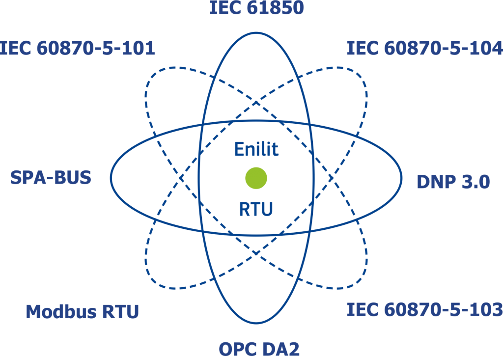
Gateway Features:
- Multi-protocol to access new and existing lEDs;
- Two-way data exchange using standard communications protocols;
- A gateway between energy protocols and OPC DA/UA for multi-vendor SCADA software;
- Parallel Redundancy Protocol (IEC 62439-3 PRP-1) supported as a standard without an extra “red box”;
- A programmable PLC logic that complies with the RTU IEC 61131-3 standard;
- Unlimited multiple sessions (Server, Client, or both) of:
- IEC 61850 (client) with PRP (IEC 62439-3 PRP-1);
- IEC 60870-5-101 (master and slave);
- IEC 60870-5-103 (master);
- IEC 60870-5-104 (client and server);
- DNP3 serial and TCP/IP (client and server);
- Modbus RTU/ASCII serial and TCP/IP (client and server);
- SPA-BUS (master);
- OPC DA2;
- Other protocols on request.
Programmable Logic Controller (PLC)
Enilit RTU can also perform as a Programmable Logic Controller (PLC). A soft logic automation tool ISaGRAF is used to provide PLC functionality. ISaGRAF is an industrial automation software technology for creating standalone controllers or distributed control systems. It is compliant to the standard IEC-61131-3 and gives great flexibility to adjust Enilit RTU hardware platform and operating system to meet any client’s needs.
Redundant RTU Solution
Hot-Standby redundancy is a default setting used in Enilit RTU.
The primary RTU and the secondary RTU systems run simultaneously. The data is mirrored to the secondary RTU system in real time what results in both systems containing identical information. This method allows fast switching from active to standby RTU modes because both RTU systems have the same data. Even if the serial connection speed is 115,200 kb/s, it is possible to transfer about 500 events per second between two RTU systems.
To support redundancy, RTUs must be connected with a minimum one LAN, RS-485, or RS-232 interface cable. These communication paths are used to exchange real-time data between the active and the standby RTUs.
It is possible to use a maximum of 4 redundant connections between RTUs.
- RS-485 or RS-232 (COM1-COM12);
- RS-485 or RS-232 (COM1-COM12);
- LAN (ETH1-ETH4);
- LAN (ETH1-ETH4).
Certificates
Enilit RTUs has been tested and certified in conformity with the following directives:
EMC Directive 2014/30/EC
IEC EN 55022:2010;
IEC EN 61000-3-2:2006;
IEC EN 55024:2010;
IEC EN 61000-4-2:2009;
IEC EN 61000-4-4:2012;
IEC EN 61000-4-5:2006;
IEC EN 61000-4-6:2014;
IEC EN 61000-4-8:2010;
IEC EN 61000-4-16:2015;
IEC EN 61000-4-17:2008;
IEC EN 61000-4-18:2011;
IEC EN 61000-4-29:2004.
LVD Directive 2014/35/EC
IEC EN 60950-1:2006/A11:2009.
Environmental testing
IEC EN 60068-2-2:2007;
IEC EN 60068-2-78:2013;
(95% RH and 40°C for 48 hrs. & 70°C for 24 hrs).
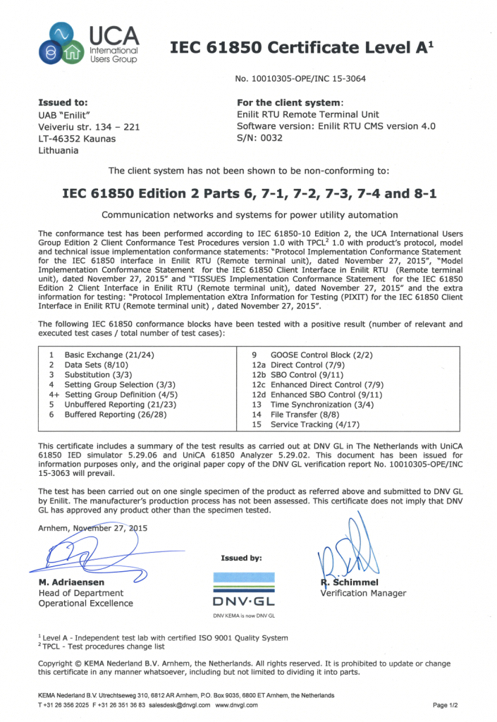
Enilit CMS software IEC 61850 Ed.2 protocol implementation tested in KEMA DNV GL
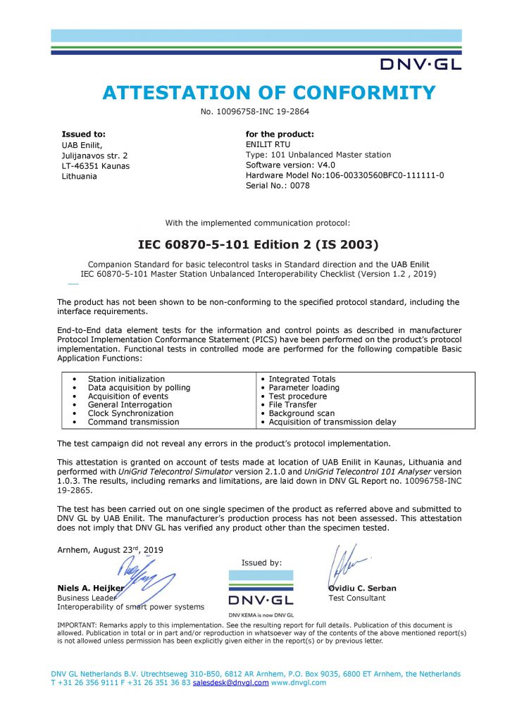
Enilit CMS software IEC 60870-5-101 master Ed.2 protocol implementation tested in KEMA DNV GL
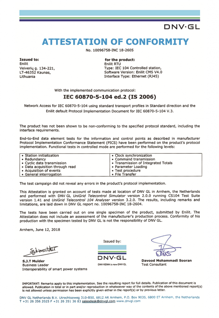
Enilit CMS software IEC 60870-5-104 Ed.2 protocol implementation tested in KEMA DNV GL
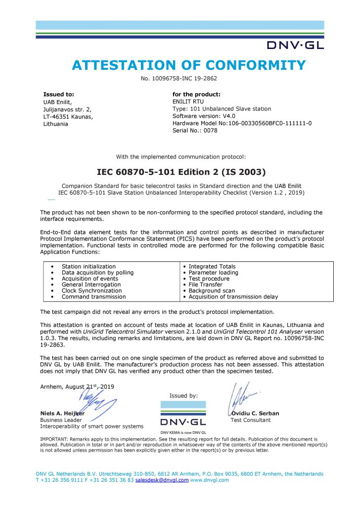
Enilit CMS software IEC 60870-5-101 slave Ed.2 protocol implementation tested in KEMA DNV GL
Documentation
Enilit CMS IEC Certificates
![]() Enilit CMS IEC 61850 Ed.2 certificate
Enilit CMS IEC 61850 Ed.2 certificate
![]() Enilit CMS IEC 60870-5-104 Ed.2 certificate
Enilit CMS IEC 60870-5-104 Ed.2 certificate
Enilit ISO Certificates
![]() UAB Enilit ISO 9001 certificate EN
UAB Enilit ISO 9001 certificate EN
![]() UAB Enilit ISO 14001 certificate EN
UAB Enilit ISO 14001 certificate EN
![]() UAB Enilit ISO 45001 certificate EN
UAB Enilit ISO 45001 certificate EN